Think of NSG and ASG as two sides of the same coin. The NSG is the actual “firewall” that enforces the rules, while the ASG is a “labeling” system that makes those rules easier to manage and understand.
🛡️ Network Security Group (NSG)
An NSG is a filter for network traffic. It contains a list of security rules that allow or deny traffic based on the “5-tuple” (Source IP, Source Port, Destination IP, Destination Port, and Protocol).
Where it lives: You associate it with a Subnet or a Network Interface (NIC).
What it does: It acts as a basic firewall for your Virtual Machines (VMs).
The Problem: If you have 50 web servers, you’d traditionally have to list all 50 IP addresses in your NSG rules. If you add a 51st server, you have to update the NSG rule. This is tedious and prone to error.
🏷️ Application Security Group (ASG)
An ASG is not a firewall itself; it is a logical object (a grouping) that you put inside an NSG rule. It allows you to group VMs together based on their function (e.g., “Web-Servers” or “DB-Servers”) regardless of their IP addresses.
Where it lives: You assign it directly to a Network Interface (NIC).
What it does: It allows you to write “natural language” rules. Instead of saying “Allow IP 10.0.0.4 to 10.0.0.5,” you can say “Allow Web-Servers to talk to DB-Servers.”
The Benefit: If you scale up and add 10 more web servers, you just tag them with the “Web-Servers” ASG. The NSG automatically applies the correct rules to them without you needing to change a single IP address in the security policy.
🔄 Key Differences at a Glance
Feature
Network Security Group (NSG)
Application Security Group (ASG)
Primary Role
The “Enforcer” (Filters traffic).
The “Organizer” (Groups VMs).
Logic
Based on IP addresses and ports.
Based on application roles/labels.
Association
Applied to Subnets or NICs.
Applied only to NICs.
Rule Limit
Up to 1,000 rules per NSG.
Used as a source/destination inside NSG rules.
Maintenance
High (must update IPs manually).
Low (rules update automatically as VMs are added).
Better Together: A Real-World Example
Imagine a 3-tier app (Web, App, Database).
You create three ASGs: ASG-Web, ASG-App, and ASG-DB.
You assign each VM to its respective ASG.
In your NSG, you create a rule: Allow Source: ASG-Web to Destination: ASG-App on Port 8080.
Now, it doesn’t matter if your web tier has 1 VM or 100 VMs—the security policy remains exactly the same and stays clean!
Would you like to see an example of how to configure these using the Azure CLI or Portal?
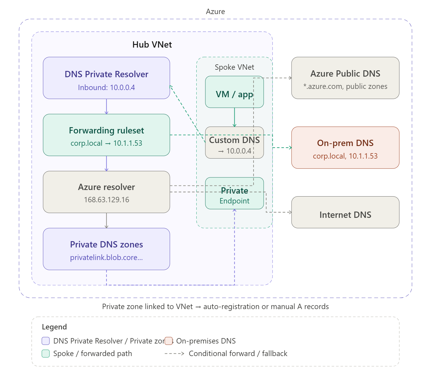
DNS in Azure is one of the most misunderstood parts of network architecture — let me build this up in two diagrams: first the overall structure of where name resolution happens, then the full query flow so you can see the decision logic in motion.
The DNS landscape in Azure
Every VNet has a built-in resolver at the special address 168.63.129.16. By default this resolves Azure public hostnames and the VNet’s own internal hostnames, but it knows nothing about your private zones or your on-premises DNS. The whole point of a DNS architecture is to extend that default with three building blocks: Private DNS Zones, DNS Private Resolver, and conditional forwarding rules.
Now let’s trace exactly what happens when a VM makes a DNS query — because the decision logic is what makes this architecture tick.Step through the query flow above. Here’s the full picture in prose:
The three building blocks
Private DNS Zones are Azure-managed authoritative zones that exist outside any VNet but get linked to VNets. When a zone is linked, 168.63.129.16 can resolve names in it from that VNet. The most important zones are the privatelink.* zones — one exists for every Azure PaaS service (Blob, SQL, Key Vault, etc.) and they map service hostnames to private endpoint IPs. Without a correct private zone, a private endpoint is useless because DNS still returns the public IP.
Auto-registration is a separate feature: link a zone named e.g. internal.contoso.com to a VNet with auto-registration enabled, and Azure automatically creates A records for every VM in that VNet. Useful for simple intra-VNet name resolution without managing records manually.
DNS Private Resolver is a fully managed, scalable DNS proxy service deployed into a VNet subnet (/28 minimum). It has two endpoint types. The inbound endpoint gets a static private IP — this is what you point all your spoke VNets’ custom DNS settings at, and what you configure on-prem DNS to forward Azure-destined queries to. The outbound endpoint is used by forwarding rulesets to reach external DNS servers (on-prem). Before DNS Private Resolver existed, people ran custom DNS VMs (Windows Server or BIND) in the hub — the resolver replaces that with a managed, zone-redundant service.
Forwarding rulesets are attached to the outbound endpoint of the resolver. They’re just ordered lists of <domain suffix> → <target DNS IP> rules. The catch-all dot (.) rule is critical — it determines where unmatched queries go. Typically that’s 168.63.129.16 so Azure private zones still work for everything else. Rulesets can be associated with multiple VNets, which makes them very powerful in hub-and-spoke: one ruleset attached to the hub propagates to all linked spokes.
The hybrid DNS loop
The trickiest part of Azure DNS is making it work symmetrically between cloud and on-premises:
On-premises → Azure: configure a conditional forwarder on your on-prem DNS server for each privatelink.* zone (and any Azure-private zones) pointing to the resolver’s inbound endpoint IP. Traffic flows: on-prem workstation → on-prem DNS → resolver inbound endpoint → 168.63.129.16 → private zone → private endpoint IP.
Azure → on-premises: configure a forwarding ruleset rule for your corporate domains (e.g. corp.local) pointing to your on-prem DNS server IP, reachable over the VPN/ExpressRoute. Traffic flows: Azure VM → resolver → ruleset matches → on-prem DNS → answer returned.
Common pitfalls
The most frequent DNS problem in Azure is a Private Endpoint resolving to its public IP instead of its private IP. This happens when the private zone isn’t linked to the VNet making the query, or when a spoke VNet is using the default 168.63.129.16 directly (bypassing the resolver) and the zone is only linked to the hub. The fix: link private zones to all VNets that need resolution, or ensure all VNets point their DNS to the resolver inbound endpoint.
The second most frequent issue is forgetting to set custom DNS on spoke VNets after creating them. The Azure default (168.63.129.16) works fine for public names but can’t do conditional forwarding. Always explicitly set the DNS server to the resolver inbound IP via the VNet’s DNS servers setting, then restart VMs so they pick up the new DHCP-assigned DNS server.
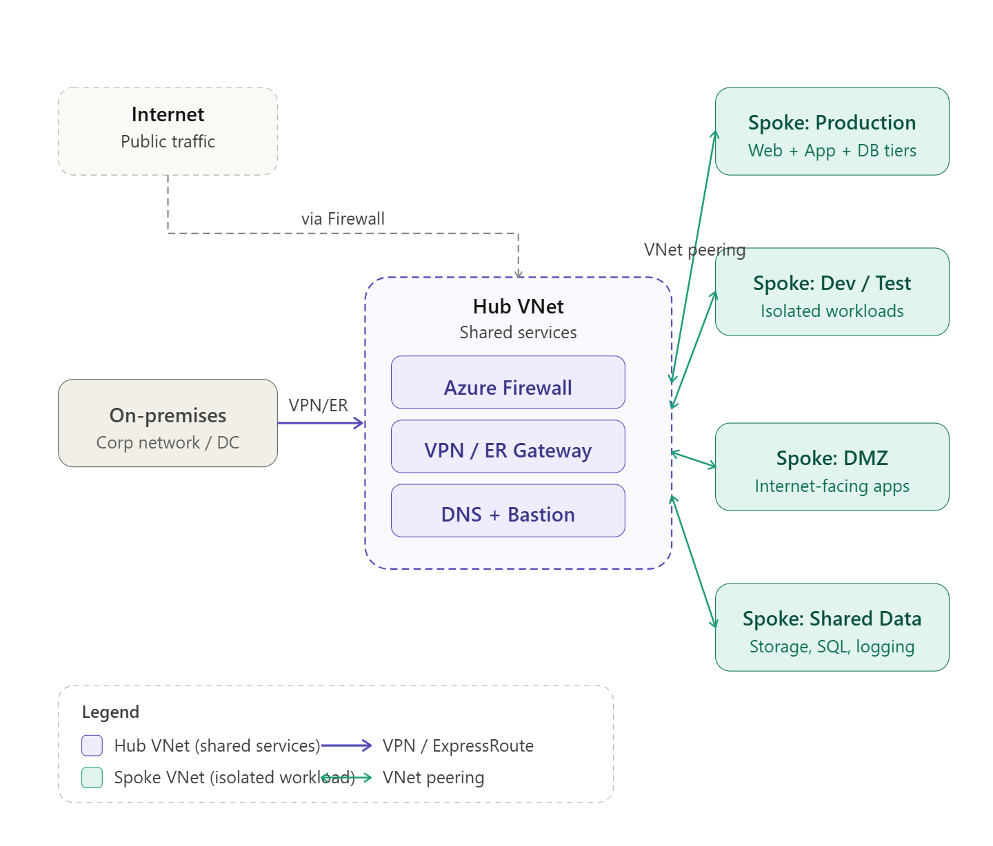
Hub-and-spoke is the most widely recommended network topology for enterprise Azure environments. The idea is simple: instead of connecting every VNet to every other VNet (which creates an unmanageable mesh of peering links and duplicate security controls), you designate one central VNet as the hub — the place where all shared infrastructure lives — and connect all other VNets as spokes that only peer with the hub.
The spokes never peer with each other directly. If Spoke A needs to talk to Spoke B, the traffic flows through the hub, which means it passes through your centralized firewall or NVA where you can inspect, log, and control it.
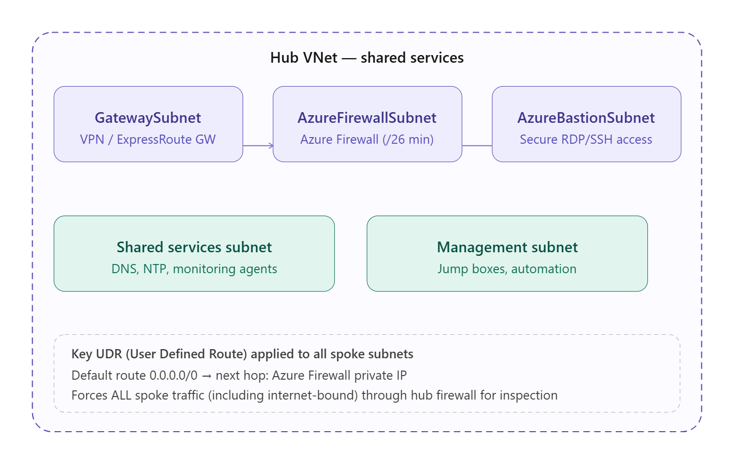
What lives in the hub
Now let’s zoom into what actually goes inside the hub VNet and why.The hub is divided into purpose-built subnets, each with a reserved name that Azure recognizes. The GatewaySubnet (name is mandatory and exact) hosts your VPN or ExpressRoute gateway for on-premises connectivity. The AzureFirewallSubnet (also exact) requires at least a /26 and hosts Azure Firewall, which becomes the traffic inspection point for everything flowing between spokes and out to the internet. AzureBastionSubnet hosts Azure Bastion, giving your operations team secure browser-based RDP/SSH to VMs in any spoke without exposing public IPs.
The UDR (User Defined Route) shown at the bottom is the mechanism that makes forced inspection work: every spoke subnet gets a route table with a default route pointing to the Azure Firewall’s private IP. This ensures no traffic can bypass the hub.
Why hub-and-spoke over full mesh?
With full mesh, connecting 5 VNets requires 10 peering links, 10 separate NSG/firewall rule sets to maintain, and no single place to audit traffic. With hub-and-spoke, you have N peering links (one per spoke), a single firewall policy to manage, centralized logging in one place, and a topology that scales linearly as you add spokes.
Traffic flows
There are three traffic paths to understand:
Spoke to spoke — traffic from Spoke A travels into the hub, hits the Azure Firewall, which evaluates your network rules, and if permitted forwards it out to Spoke B. Neither spoke knows about the other at the routing level; they only know the hub’s firewall IP as their default gateway.
Spoke to internet — the UDR default route sends internet-bound traffic to the Firewall rather than out directly. The Firewall applies application rules (FQDNs, categories), performs SNAT, and egresses through its own public IP. This gives you a single, auditable egress point for the entire organization.
On-premises to spoke — traffic from your corporate network arrives via VPN or ExpressRoute into the GatewaySubnet, then routes through the Firewall before reaching any spoke. Gateway transit (enabled on the hub side of each peering, “use remote gateways” on the spoke side) lets all spokes share a single gateway.
Key design decisions and best practices
Address space planning is everything. The hub needs enough space for its subnets (Gateway needs at least /27, Firewall needs /26, Bastion needs /26). Spokes should get their own non-overlapping /16 or /24 ranges. Plan for future growth — you can’t resize after peering.
Use Azure Firewall Policy, not classic Firewall rules. Policy objects can be shared across multiple Firewall instances in different regions, making multi-region hub-and-spoke consistent.
NSGs at every spoke subnet. The Firewall is your perimeter, but NSGs at the subnet level are your last line of defence. They provide micro-segmentation even if a firewall rule is misconfigured.
One hub per region. In a multi-region setup, deploy a hub in each region. Spokes peer to their regional hub. The two hubs can be globally peered to each other, but remember: gateway transit does not work over global peering, so on-premises routes to remote-region spokes need careful planning (usually handled via BGP and ExpressRoute Global Reach, or Azure Virtual WAN).
Consider Azure Virtual WAN for large scale. If you have dozens of spokes, branches, and multiple regions, Azure Virtual WAN automates hub management, routing, and scaling. It’s hub-and-spoke as a managed service.
Tag everything. Use resource tags (environment, cost-center, spoke-owner) consistently on VNets and peering resources so you can attribute costs and audit ownership as the topology grows.
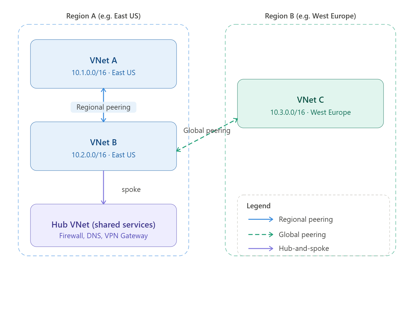
VNet peering connects two Azure Virtual Networks so that resources in each can communicate with each other using private IP addresses, routing traffic over the Microsoft backbone — never the public internet. From the VM’s perspective, the remote VNet feels like it’s on the same network.
There are two types:
Regional peering connects VNets within the same Azure region. Traffic stays entirely within that region’s backbone, latency is minimal, and there is no bandwidth cost for the traffic itself (though egress charges apply in some configurations).
Global peering connects VNets across different Azure regions. It uses the same private backbone but crosses the WAN layer between regions. This incurs additional data transfer charges and has a few extra restrictions (covered below).
How it works under the hood
Peering is non-transitive by design. If VNet A peers with VNet B, and VNet B peers with VNet C, VNet A cannot reach VNet C through B automatically. This is intentional — it keeps the blast radius of any misconfiguration small and forces deliberate topology decisions. To allow A–C traffic, you must either peer them directly or use a Network Virtual Appliance (NVA) or Azure Firewall as a transit hub.
Peering is also directional: each side must create its own peering link pointing to the other. Both links must exist and be in “Connected” state before traffic flows.
Key restrictions
Address space: The two VNets being peered must have non-overlapping CIDR ranges. This is the most common cause of failed peerings — plan your IP space carefully before deploying. You cannot resize a VNet’s address space after peering without first removing and re-adding the peering.
No transitivity (without help): As noted above, peering is point-to-point only. Traffic does not flow through an intermediate VNet unless you explicitly route it via an NVA or gateway.
Gateway transit limits (global peering): You cannot use a VPN Gateway or ExpressRoute Gateway in a remote VNet for on-premises connectivity over a global peer. Gateway transit is supported for regional peering but not for global peering. This is the biggest operational gotcha for global peerings.
Basic Load Balancer: Resources behind an Azure Basic SKU Load Balancer in one peered VNet are not reachable from the other VNet. Standard SKU Load Balancer works fine. Microsoft has largely deprecated Basic LB anyway.
IPv6: Dual-stack (IPv4 + IPv6) peering is supported, but you must configure both address families explicitly.
Subscription and tenant: You can peer VNets across different subscriptions and even across different Azure AD tenants, but this requires explicit authorization on both sides and the right RBAC roles (Network Contributor or a custom role with Microsoft.Network/virtualNetworks/peer/action).
Best practices
Plan your IP addressing first. This is the cardinal rule. Overlapping CIDRs cannot be peered, and changing address space after the fact is painful. Use RFC 1918 space systematically — e.g. one /16 per major environment, subdivided by region and VNet purpose.
Use hub-and-spoke. Rather than full-mesh peering (N×(N−1) peering links between N VNets), peer all spoke VNets to a central hub that hosts shared services: Azure Firewall, DNS resolvers, VPN/ExpressRoute gateways. This centralises traffic inspection and keeps the number of peering links manageable. Azure Virtual WAN automates much of this for large-scale deployments.
Enable gateway transit deliberately. If spoke VNets need to reach on-premises networks via a hub gateway, enable “Allow gateway transit” on the hub side and “Use remote gateways” on the spoke side. Be aware this only works for regional peering.
Monitor with Network Watcher. Use Connection Monitor and VNet Flow Logs to validate that peered traffic is flowing as expected and to detect routing anomalies early.
Tag and document peerings. Peering links don’t carry tags natively, but you should document each peering in your infrastructure-as-code (Bicep/Terraform) with clear naming conventions — e.g. peer-hubeastus-to-spokeeastus-app1 — so intent is obvious six months later.
Use NSGs on subnets, not VNets. Peering opens the network path, but you still control traffic with Network Security Groups at the subnet level. Don’t assume peering = trusted; apply least-privilege NSG rules between peered VNets just as you would for any other traffic.
Prefer Infrastructure-as-Code. Peering configuration done manually in the portal is error-prone (easy to create only one side). Terraform’s azurerm_virtual_network_peering or Bicep’s Microsoft.Network/virtualNetworks/virtualNetworkPeerings resource create both sides atomically.
Regional vs global at a glance
Regional
Global
Latency
Lower (same region backbone)
Higher (cross-region WAN)
Data transfer cost
Lower / free in some cases
Additional per-GB charges
Gateway transit
✓ Supported
✗ Not supported
Basic LB reachability
✗ Not supported
✗ Not supported
Typical use case
App tiers, dev/prod separation
Disaster recovery, multi-region apps
Click any VNet in the diagram above to dive deeper into a specific aspect.
Managing cross-spoke traffic—often called East-West traffic—is a critical design challenge in large-scale Azure environments. As of 2026, the shift toward Zero Trust and automated routing has made traditional manual User-Defined Routes (UDRs) less sustainable for large enterprises.
Depending on your scale and security requirements, here are the preferred strategies for managing this traffic.
1. The Modern Enterprise Standard: Azure Virtual WAN (vWAN)
For environments with dozens or hundreds of spokes, Azure Virtual WAN with a Secured Hub is the gold standard. It replaces the manual effort of managing peering and route tables.
How it works: You deploy a Virtual Hub and connect spokes to it. By enabling Routing Intent, you tell Azure to automatically attract all East-West traffic to an Azure Firewall (or supported third-party NVA) within the hub.
Why it’s preferred:
Auto-propagation: No need to manually create UDRs in every spoke to point to a central firewall; the hub manages the route injection.
Transitive Routing: vWAN provides “any-to-any” connectivity by default, solving the non-transitive nature of standard VNet peering.
Scale: It is designed to handle thousands of connections and massive throughput across multiple regions.
2. The Granular Control Approach: Hub-and-Spoke with Azure Virtual Network Manager (AVNM)
If you prefer a traditional Hub-and-Spoke model but want to avoid the “UDR Hell” of manual updates, Azure Virtual Network Manager (AVNM) is the strategic choice.
Strategy: Use AVNM to define Network Groups (e.g., “Production-Spokes”). AVNM can then automatically:
Create and manage VNet peerings.
Deploy Admin Rules (security) and Routing Rules (UDRs) across all VNets in a group.
Best For: Environments that require high customization or the use of specific third-party NVAs that may not yet be fully integrated into the vWAN “Managed” model.
3. The “Service-First” Strategy: Azure Private Link
Not all cross-spoke traffic needs to be “network-level” (Layer 3). For communication between applications (e.g., a web app in Spoke A talking to a database in Spoke B), Private Link is often superior to VNet peering.
Strategy: Instead of peering the entire VNets, expose the specific service in Spoke B via a Private Link Service. Spoke A then consumes it via a Private Endpoint.
Why it’s preferred:
Isolation: It eliminates the risk of lateral movement across the network because the VNets are not actually “connected.”
IP Overlap: It allows spokes with overlapping IP ranges to communicate, which is impossible with standard peering.
Security: Traffic stays on the Microsoft backbone and is mapped to a specific resource, reducing the attack surface.
4. Architectural Comparison: At-a-Glance
Feature
Standard Peering + UDR
Virtual WAN (Secured Hub)
Private Link
Complexity
High (Manual)
Low (Automated)
Medium (Per-service)
Transitivity
None (requires NVA/UDR)
Native
N/A (Service-based)
Scale
Hard to maintain
Excellent
Excellent
Security
NSG + Firewall NVA
Integrated Firewall
Least Privilege (Resource-level)
5. Critical Best Practice: “Zero Trust” at the Spoke
Regardless of the routing strategy, large environments should implement Micro-segmentation within the spokes.
NSGs and ASGs: Use Network Security Groups (NSGs) combined with Application Security Groups (ASGs) to control traffic between subnets within the same spoke.
Explicit Outbound (2026 Change): Note that as of March 31, 2026, Azure has retired “Default Outbound Access.” You must now explicitly define outbound paths (NAT Gateway or Firewall) for all spokes, which prevents accidental “leaking” of traffic to the internet while managing your internal East-West flows.
Designing a large-scale Azure environment from scratch in 2026 requires moving away from “bespoke” networking toward a Productized Infrastructure model.
The most robust strategy follows the Azure Landing Zone (ALZ) conceptual architecture, utilizing Azure Virtual WAN (vWAN) as the connectivity backbone. This setup minimizes manual routing while providing maximum security.
1. The Foundation: Management Group Hierarchy
Before touching a VNet, you must organize your governance. Use Management Groups to enforce “Guardrails” (Azure Policy) that automatically configure networking for every new subscription.
Root Management Group
Platform MG: Contains the Connectivity, Identity, and Management subscriptions.
Landing Zones MG: * Corp MG: For internal workloads (connected to the Hub).
Online MG: For internet-facing workloads (isolated or DMZ).
Sandbox MG: For disconnected R&D.
2. The Network Backbone: Virtual WAN with Routing Intent
In a greenfield 2026 design, Virtual WAN (Standard SKU) is the preferred “Hub.” It acts as a managed routing engine.
The “Routing Intent” Strategy
Traditional hubs require you to manually manage Route Tables (UDRs) in every spoke. With Routing Intent enabled in your Virtual Hub:
Centralized Inspection: You define that “Private Traffic” (East-West) must go to the Azure Firewall in the Hub.
Auto-Propagation: Azure automatically “attracts” the traffic from the spokes to the Firewall. You no longer need to write a 0.0.0.0/0 or 10.0.0.0/8 UDR in every spoke.
Inter-Hub Routing: If you expand to another region (e.g., East US to West Europe), vWAN handles the inter-region routing natively without complex global peering strings.
3. The Security Strategy: Micro-segmentation
Don’t rely solely on the central Firewall; it’s too “coarse” for large environments. Use a layered approach:
North-South (Internet): Managed by Azure Firewall Premium in the vWAN Hub (IDPS, TLS Inspection).
East-West (Cross-Spoke): Managed by Routing Intent + Azure Firewall.
Intra-Spoke (Subnet-to-Subnet): Use Network Security Groups (NSGs) and Application Security Groups (ASGs).
Tip: Use Azure Virtual Network Manager (AVNM) to deploy “Security Admin Rules” that stay at the top of the NSG stack across all spokes, preventing developers from accidentally opening SSH/RDP to the world.
4. The “Subscription Vending” Machine
In 2026, you shouldn’t “build” a spoke; you should “vend” it. When a team needs a new environment:
A CI/CD pipeline (Terraform/Bicep) creates a new Subscription.
Azure Policy automatically moves it to the Corp Management Group.
Policy triggers the creation of a Spoke VNet and Peerings to the vWAN Hub.
Routing Intent automatically secures the traffic without the team ever seeing a Route Table.
5. Architectural Blueprint (Summary)
Component
Recommendation
Topology
Azure Virtual WAN (vWAN) Hub-and-Spoke.
Routing Control
Routing Intent (Standard Hub) to eliminate manual UDRs.
Governance
Azure Virtual Network Manager (AVNM) for global security rules.
Internal Comms
Private Link for sensitive PaaS-to-PaaS traffic (SQL, Storage).
Automation
Infrastructure as Code (Bicep/Terraform) via ALZ Accelerators.
Implementation Pro-Tip
Since you are starting from scratch, ensure you implement Azure DDoS Protection on the Hub IP addresses and enable Diagnostic Settings to a central Log Analytics Workspace immediately. In 2026, observability is not an “add-on”—it’s a requirement for troubleshooting the automated routing of vWAN.
Since you’re using Terraform, you have the advantage of leveraging the Azure Verified Modules (AVM) and the ALZ (Azure Landing Zones) Terraform module. These are the industry standard for codifying the “Hub-and-Spoke” architecture with Virtual WAN.
Here is the architectural design and the strategic Terraform implementation path for your greenfield environment.
1. The Terraform-Centric Architecture
The goal is to treat your network as a “platform” that provides services to “application” spokes.
Core Components
Virtual WAN Module: Deploys the azurerm_virtual_wan and azurerm_virtual_hub.
Secured Hub: Deploy azurerm_firewall within the hub.
Routing Intent: Configures azurerm_virtual_hub_routing_intent to point all $0.0.0.0/0$ (Internet) and private traffic (Internal) to the firewall.
Spoke Vending: A reusable module that creates a VNet, subnets, and the azurerm_virtual_hub_connection.
2. Recommended Terraform Structure
For a large environment, do not put everything in one state file. Use a layered approach with remote state lookups or specialized providers.
Layer 1: Foundation (Identity & Governance)
Deploys Management Groups and Subscription aliases.
Sets up the Terraform Backend (Azure Storage Account with State Locking).
Layer 2: Connectivity (The “Hub”)
Deploys the vWAN, Hubs, Firewalls, and VPN/ExpressRoute Gateways.
Crucial Logic: Define your routing_intent here. This ensures that the moment a spoke connects, it is governed by the central firewall.
Layer 3: Landing Zones (The “Spokes”)
Use a Terraform For_Each loop or a Spoke Factory pattern.
Each spoke is its own module instance, preventing a single “blast radius” if one VNet deployment fails.
3. Handling “East-West” Traffic in Code
With vWAN and Routing Intent, your Terraform code for a spoke becomes incredibly simple because you omit the azurerm_route_table.
# Routing Intent at the Hub level handles the traffic redirection,
# so no complex 'routing' block is needed here for East-West inspection.
}
4. Addressing Modern Constraints (2026)
Provider Constraints: Ensure you are using azurerm version 4.x or higher, as many vWAN Routing Intent features were stabilized in late 2024/2025.
Orchestration: Use Terraform Cloud or GitHub Actions/Azure DevOps with “OIDC” (Workload Identity) for authentication. Avoid using static Service Principal secrets.
Policy as Code: Use the terraform-azurerm-caf-enterprise-scale module (often called the ALZ module) to deploy Azure Policies that deny the creation of VNets that aren’t peered to the Hub.
5. Summary of Design Benefits
Zero UDR Maintenance: Routing Intent removes the need to calculate and update CIDR blocks in Route Tables every time a new spoke is added.
Scalability: Terraform can stamp out 100 spokes in a single plan/apply cycle.
Security by Default: All cross-spoke traffic is forced through the Firewall IDPS via the Hub connection logic.
Would you like to see a more detailed code snippet for the vWAN Routing Intent configuration, or should we look at how to structure the Spoke Vending module?
Before DNS Private Resolver existed, if you wanted to resolve Azure Private DNS Zone records from on-premises, or forward on-premises domain queries from Azure, you had to run a custom DNS forwarder VM (e.g., Windows DNS Server or BIND on a Linux VM). This meant managing, patching, scaling, and ensuring high availability of that VM yourself — a maintenance burden and a potential single point of failure.
Azure DNS Private Resolver eliminates that entirely.
What It Is
Azure DNS Private Resolver is a fully managed, cloud-native DNS service deployed inside your VNet that acts as a bridge between:
Azure (Private DNS Zones, VNet-internal resolution)
On-premises networks (your corporate DNS servers)
It handles DNS queries coming in from on-premises and DNS queries going out from Azure — without any VMs to manage.
How It Works — The Two Endpoints
The resolver has two distinct components:
1. Inbound Endpoint
Gets assigned a private IP address inside your VNet
On-premises DNS servers can forward queries to this IP over ExpressRoute or VPN
Allows on-premises clients to resolve Azure Private DNS Zone records — something that was previously impossible without a forwarder VM
Example use case: on-premises user needs to resolve mystorageaccount.privatelink.blob.core.windows.net to its private IP
2. Outbound Endpoint
Used with DNS Forwarding Rulesets
Allows Azure VMs to forward specific domain queries to external DNS servers (e.g., on-premises DNS)
Example use case: Azure VM needs to resolve server01.corp.contoso.local which only exists on-premises
DNS Forwarding Rulesets
A Forwarding Ruleset is a set of rules attached to the Outbound Endpoint that says:
Domain
Forward To
corp.contoso.local
10.0.0.5 (on-prem DNS)
internal.company.com
10.0.0.6 (on-prem DNS)
. (everything else)
Azure default resolver
Rulesets are associated with VNets, so multiple Spokes can share the same ruleset without duplicating configuration.
How It Fits Into Hub-and-Spoke
In an enterprise Hub-and-Spoke architecture, DNS Private Resolver lives in the Hub VNet and serves all Spokes centrally:
On-Premises DNS
│
│ (conditional forward)
▼
DNS Private Resolver ──► Inbound Endpoint (resolves Azure Private DNS Zones)
│
│ (outbound ruleset)
▼
On-Premises DNS (for corp.contoso.local queries from Azure VMs)
Spoke VNets ──► point DNS setting to Private Resolver inbound IP
All Spoke VNets are configured to use the resolver’s inbound endpoint IP as their DNS server, giving every workload consistent, centralized DNS resolution.
Key Benefits Over a Forwarder VM
DNS Forwarder VM
DNS Private Resolver
Management
You manage patching, reboots, scaling
Fully managed by Microsoft
Availability
You build HA (2 VMs, load balancer)
Built-in high availability
Scalability
Manual VM resizing
Scales automatically
Cost
VM + disk + load balancer costs
Pay per endpoint per hour
Security
VM attack surface
No VM, no management ports
Integration
Manual config to reach Azure DNS
Native Azure DNS integration
A Real-World DNS Flow Example
Scenario: On-premises user wants to access a Storage Account via its private endpoint.
User’s machine queries on-premises DNS for mystorageaccount.privatelink.blob.core.windows.net
On-premises DNS has a conditional forwarder: send privatelink.blob.core.windows.net queries → DNS Private Resolver inbound endpoint IP
DNS Private Resolver receives the query
It checks the Azure Private DNS Zone linked to the Hub VNet
Finds the A record → returns the private endpoint IP (e.g., 10.1.2.5)
Traffic flows from on-premises over ExpressRoute directly to the private endpoint — never touching the public internet
In One Sentence
Azure DNS Private Resolver is a managed service that sits inside your VNet and acts as the intelligent DNS bridge between your on-premises network and Azure — handling both inbound queries from on-premises and outbound forwarding from Azure, without any VMs to maintain.
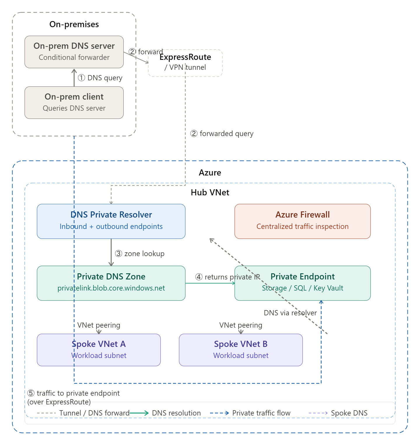
Here is how to read the diagram step by step:
① Query starts — An on-premises client needs to resolve a private endpoint hostname (e.g. mystorageaccount.privatelink.blob.core.windows.net). It asks the on-premises DNS server.
② Conditional forwarding — The on-premises DNS server has a conditional forwarder rule for privatelink.* domains. It forwards the query through the ExpressRoute/VPN tunnel to the DNS Private Resolver’s inbound endpoint IP inside the Hub VNet.
③ Zone lookup — The DNS Private Resolver receives the query and checks the linked Private DNS Zone inside Azure, which holds the A record for the private endpoint.
④ Private IP returned — The zone returns the private endpoint’s internal IP address (e.g. 10.1.2.5) — never the public IP — back through the chain to the on-premises client.
⑤ Traffic flows privately — The client now connects directly to that private IP over ExpressRoute, completely bypassing the public internet. Traffic never touches a public endpoint.
Spoke VNets inside Azure follow the same pattern — their DNS settings point to the resolver, and all resolution flows through the Hub centrally. Click any box in the diagram to explore that component further.
Great question — this is one of the trickiest concepts in hybrid Azure networking. Here is the full picture:
The Core Challenge
By default, Azure Private DNS Zones are only visible inside Azure VNets that are linked to them. An on-premises client has no way to query them directly — it sits outside Azure entirely. So without special architecture, an on-premises client resolving mystorageaccount.privatelink.blob.core.windows.net would get the public IP back, defeating the purpose of a private endpoint.
The solution is to build a DNS resolution chain that bridges on-premises and Azure.
The Resolution Chain — Step by Step
Step 1 — Client queries its local DNS
The on-premises client (laptop, server, application) sends a DNS query to its configured DNS server, just as it always would. Nothing special happens at the client level — it has no knowledge of Azure.
Step 2 — On-premises DNS checks its conditional forwarder
The on-premises DNS server (Windows DNS, BIND, etc.) has a conditional forwarder rule configured by your network team that says:
“Any query for privatelink.blob.core.windows.net — don’t try to resolve it yourself. Forward it to this IP address instead.”
That IP address is the inbound endpoint of Azure DNS Private Resolver, which is a private IP routable over ExpressRoute or VPN (e.g. 10.0.1.4).
Step 3 — Query travels over ExpressRoute or VPN
The forwarded query travels from on-premises, through the private tunnel, and arrives at the DNS Private Resolver’s inbound endpoint inside the Hub VNet. This is just a UDP packet on port 53 — it looks like any other DNS query.
Step 4 — DNS Private Resolver checks the Private DNS Zone
The resolver receives the query and uses Azure’s built-in DNS (168.63.129.16) to look up the answer. Because the Hub VNet is linked to the Private DNS Zone for privatelink.blob.core.windows.net, it can see the A record inside that zone — which contains the private endpoint’s internal IP (e.g. 10.1.2.5).
Step 5 — Private IP is returned all the way back
The resolver returns 10.1.2.5 back through the tunnel to the on-premises DNS server, which passes it back to the client. The client now has the private IP, not the public one.
Step 6 — Traffic flows privately
The client connects to 10.1.2.5 directly over ExpressRoute or VPN. The traffic never touches the public internet — it flows entirely over your private network into Azure.
What Has to Be in Place
For this to work, several things must be correctly configured:
On the Azure side:
Azure DNS Private Resolver deployed in the Hub VNet with an inbound endpoint assigned a private IP
The relevant Private DNS Zone (e.g. privatelink.blob.core.windows.net) linked to the Hub VNet
An A record in that zone pointing to the private endpoint’s IP
The inbound endpoint’s IP must be reachable from on-premises over ExpressRoute or VPN (NSGs and routing must allow UDP 53)
On the on-premises side:
A conditional forwarder on the on-premises DNS server for each privatelink.* domain pointing to the resolver’s inbound endpoint IP
Note: you need a separate conditional forwarder per private link zone (blob, sql, vault, etc.) — there is no wildcard forwarder for all privatelink.* in most DNS servers
The Most Common Misconfiguration
The single most frequent mistake is when Azure VMs also use a custom DNS server (e.g. a forwarder VM), and that custom server does not forward privatelink.* queries to Azure’s resolver at 168.63.129.16.
The result: the custom DNS server tries to resolve the private endpoint hostname itself, fails to find it, and either returns the public IP or returns nothing. The fix is always to ensure your custom DNS server has a forwarder rule sending privatelink.* queries to 168.63.129.16 before any other resolution is attempted.
Why You Can’t Just Use Azure Public DNS from On-Premises
You might wonder — why not just point on-premises clients directly at Azure’s public DNS? The answer is that Azure’s public DNS (168.63.129.16) is a link-local address, only reachable from inside an Azure VNet. It is not routable from on-premises at all. That is precisely why the DNS Private Resolver inbound endpoint exists — it gives you a routable private IP that acts as the on-ramp into Azure’s DNS infrastructure.
In short: the on-premises client never knows any of this is happening. It asks its local DNS, the local DNS quietly forwards to Azure via the tunnel, Azure resolves using its private zone, and the private IP comes back. The entire chain is transparent to the end user.
Would you like a diagram showing this flow for a specific service like Storage or SQL, or would you like to go deeper on the conditional forwarder setup?
Managing DNS in a hybrid environment (Azure + On-premises) can feel like a high-stakes game of “telephone.” As of 2026, the industry standard has moved away from the old “DNS Forwarder VMs” and settled on the Azure DNS Private Resolver.
Here are the primary resolution patterns you should know to keep your traffic flowing smoothly over VPN or ExpressRoute.
1. The Modern Hub-Spoke Pattern (Azure DNS Private Resolver)
This is the recommended architecture. It uses a managed service instead of VMs, reducing overhead and providing built-in high availability.
How it Works:
Azure to On-Prem: You create an Outbound Endpoint in your Hub VNet and a Forwarding Ruleset. You link this ruleset to your Spoke VNets. When an Azure VM tries to resolve internal.corp.com, Azure DNS sees the rule and sends the query to your on-premises DNS servers.
On-Prem to Azure: You create an Inbound Endpoint (a static IP in your VNet). On your local Windows/Linux DNS servers, you set up a Conditional Forwarder for Azure zones (like privatelink.blob.core.windows.net) pointing to that Inbound Endpoint IP.
2. The “Private Link” Pattern (Split-Brain Avoidance)
One of the biggest “gotchas” in hybrid setups is resolving Azure Private Endpoints. If you aren’t careful, your on-premises machine might resolve the public IP of a storage account instead of the private one.
The Pattern: Always forward the public service suffix (e.g., blob.core.windows.net) to the Azure Inbound Endpoint, not just the privatelink version.
Why: Azure DNS is “smart.” If you query the public name from an authorized VNet, it automatically checks for a matching Private DNS Zone and returns the private IP. If you only forward the privatelink zone, local developers have to change their connection strings, which is a massive headache.
3. Legacy DNS Forwarder Pattern (IaaS VMs)
While largely replaced by the Private Resolver, some organizations still use Domain Controllers or BIND servers sitting in a Hub VNet.
Feature
VM-based Forwarders
Azure DNS Private Resolver
Management
You patch, scale, and backup.
Fully managed by Microsoft.
Availability
Requires Load Balancers/Availability Sets.
Built-in 99.9% – 99.99% SLA.
Cost
High (Compute + Licenses + Management).
Consumption-based (often cheaper).
Complexity
High (Custom scripts for sync).
Low (Native ARM/Terraform support).
4. Key Configuration Rules for 2026
The 168.63.129.16 Rule: This is the “Magic IP” for Azure DNS. You cannot query this IP directly from on-premises. You must use an Inbound Endpoint as a bridge.
VNet Delegation: Remember that the subnets used for Private Resolver endpoints must be delegated specifically to Microsoft.Network/dnsResolvers. You can’t put VMs or other resources in those subnets.
Avoid Recursive Loops: Never point an Azure Outbound Forwarder to an on-premises server that is also configured to forward those same queries back to Azure. This creates a “DNS death loop” that will drop your resolution performance to zero.
Pro-Tip: If you are using Azure Virtual WAN, the DNS Private Resolver can be integrated into the Hub, allowing all connected spokes and branches to share the same resolution logic without redundant configurations.
Starting a fresh greenfield deployment?
For a greenfield deployment in 2026, you have the advantage of skipping the “technical debt” of legacy VM forwarders. The goal is a Hub-and-Spoke architecture using the Azure DNS Private Resolver.
This setup ensures that your on-premises office and your Azure cloud act as a single, cohesive network for naming.
1. The Essential Architecture
In a greenfield setup, you should centralize the resolver in your Hub VNet.
Inbound Endpoint: Provides a static IP address in your Hub VNet. Your on-premises DNS servers (Windows/BIND) will use this as a Conditional Forwarder.
Outbound Endpoint: A dedicated egress point that Azure DNS uses to send queries out to your on-premises DNS.
Forwarding Ruleset: A logic engine where you define: “If a query is for corp.local, send it to On-Prem IP 10.50.0.4.”
2. Step-by-Step Implementation Strategy
Step 1: Subnet Design (Non-Negotiable)
The Private Resolver requires two dedicated subnets in your Hub VNet. They cannot contain any other resources (no VMs, no Gateways).
Subnet 1 (Inbound): Min /28. Delegate to Microsoft.Network/dnsResolvers.
Subnet 2 (Outbound): Min /28. Delegate to Microsoft.Network/dnsResolvers.
Step 2: The “Private Link” Rule of Thumb
To avoid the common “2026 DNS Trap” where resolution fails for Private Endpoints, do not just forward privatelink zones.
On-Prem Config: Create conditional forwarders for the public suffixes (e.g., blob.core.windows.net, database.windows.net) pointing to your Azure Inbound Endpoint IP.
Why? This allows the Azure Resolver to handle the logic. If a Private Endpoint exists, it returns the private IP. If not, it returns the public IP. This keeps your application connection strings identical regardless of where the app sits.
Step 3: Global Reach (Spoke VNets)
You don’t need a resolver in every spoke.
Link your Forwarding Ruleset to every Spoke VNet.
This instantly gives all spokes the ability to resolve on-premises names without changing their DNS server settings from “Azure Provided.”
3. Financial Blueprint (2026 Pricing)
Budgeting for this is straightforward but requires awareness of the “Base Fee.”
Component
Estimated Cost (Monthly)
Inbound Endpoint
~$180
Outbound Endpoint
~$180
Forwarding Ruleset
~$2.50
Query Processing
~$0.60 per million queries
Total Base
~$362.50 / month
4. Greenfield “Gotchas” to Avoid
DNS Loops: Never link a Forwarding Ruleset to the same VNet where the Inbound Endpoint lives if that ruleset contains a rule pointing back to that Inbound Endpoint. You’ll create a recursive loop that crashes resolution.
The 168.63.129.16 Myth: In 2026, some older documentation still suggests querying the Azure WireServer IP directly from on-prem. This will not work. Traffic to this IP is only routable within the Azure backbone.
Subnet Sizing: While /28 is the minimum, if you plan on a massive global architecture with dozens of endpoints, consider a /27 to avoid future re-addressing headaches.
deploy this via Terraform
Deploying a Private DNS Resolver via Terraform requires a specific sequence of resources. In a greenfield scenario, you’ll likely want to use the Azure Verified Modules (AVM) or the standard azurerm provider resources.
Here is the “cleanest” implementation using standard azurerm resources for a Hub-and-Spoke architecture.
1. Subnet Delegation (The Foundation)
You cannot use standard subnets. You must delegate them to Microsoft.Network/dnsResolvers.
Trailing Dots: Always include the trailing dot in domain_name (e.g., internal.com.). If omitted, some versions of the provider may show a perpetual “diff” in your plan.
IP Outputs: Since the Inbound Endpoint uses dynamic allocation, use an output block to capture the IP address. You’ll need this IP to configure the conditional forwarders on your On-Premises DNS servers.Terraformoutput "dns_inbound_ip" { value = azurerm_private_dns_resolver_inbound_endpoint.inbound.ip_configurations[0].private_ip_address }
Lifecycle Management: Endpoints can take 10-15 minutes to deploy. If you are running this in a CI/CD pipeline, ensure your timeout settings are sufficient.
Does your current Terraform setup include a central “Hub” module where this configuration would live?